Scaled Claw Machine
Claw Machine Project
In my EGR1000L class, the professor assigned a group project with the following requirements:
1. Contain three independent mechanical movements
2. Stay within 12″x12″x12″ dimensions
3. Keep under an $80 budget
My team decided to attempt a miniature claw machine. The specifications by the professor required the project to only work by flipping a switch, therefore no joystick control was included.
Video Demo
This video demo shows the claw machine working!
The project is only designed to move in the x and y directions in order to reduce complexity while still easily meeting the requirements.
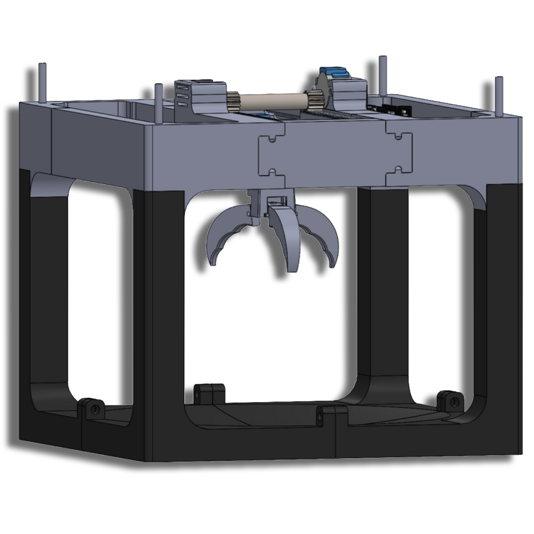
The three independent mechanical movements in the claw machine is the left/right movement of the gantry (my design), the lowering and raising of the claw, and the gripping/ungripping of the claw.
Takeaways
The gantry system (left and right movement) needed some testing and fine tuning, but the system worked.
The claw raising/lowering and gripping/ungripping was a less reliable system. This is mostly due to the communication disconnect between the designer of the claw and me. We worked on our parts independently, and I implemented a place for a motor and a servo to act upon on the claw via strings.
If there was more teamwork and communication involved, the outcome would have been more reliable.
My Contribution
My role in the project was to design the supports and gantry system to move the claw left and right. I also played a crucial role in the integration of the claw, which was modeled by a fellow classmate.
The main sections I made can be categorized into two main sections:
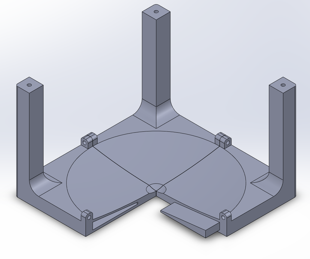
1. The Base Structure
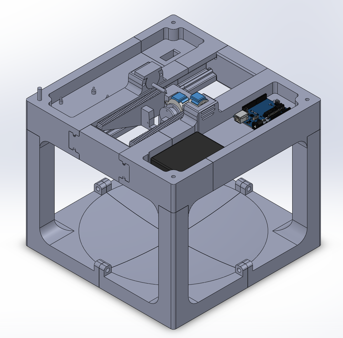
2. The Gantry System
The base structure is the foundation of the machine, which the project rests upon. I initially modeled this in a single part, without taking into consideration that the print would be too big for the Bambu P1S 3D printer that I was using.
After some iteration, tolerancing, and testing in an assembly. I fell upon the final base structure design.
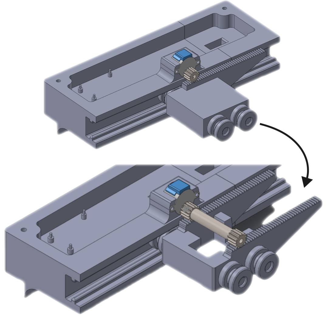
The gantry system was more complicated. The idea was to simply rotate a gear with a motor, and use a rack to create a linear motion on a rolling platform in the middle.
The first model applied the gear torque on rack which was not centered on the rolling platform. I was concerned force being applied away from the center would lead to the platform trying to ‘rotate’ about its center and jam itself into the wall.
Whether or not that was a valid concern, I won’t be able to test. We didn’t have the budget or time to test multiple iterations, so I designed a different gear and rolling platform that mitigated that issue.
The second model of the gantry has an extended gear with two racks on the sides of the moving platform. This allows for the force applied to the moving platform to be symmetrical and average at the center, leading to smoother rolling and a better force distribution.
The low budget and time available for this project led to me meticulously testing the parts in assemblies and reviewing tolerances in order to mitigate the need for reprints.
Conclusion
This claw machine project created a valuable learning experience in teamwork, collaboration, and communication.
I was happy to apply the modelling skills that I learned while working on Project AMP. The project helped me learn more about the research side, the electronics, and the engineering design process actually applied.
As a first year project, I feel satisfied with the result. There is plenty of room for improvement, and I would have approached this project differently knowing what I do now.
But ultimately we met the project requirements despite tightly meeting the deadline, and while this miniature claw machine may lack much reliability, my projects and work in the future will gain from the lessons I learned here.